
ATLAS e-News
23 February 2011
Keeping cool under pressure
25 January 2011
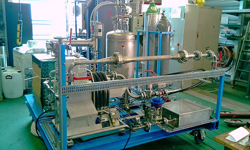
The new blending machine under construction in the workshop
It has been over two years since we last checked in with the Inner Detector cooling folks. Theirs has been a rough ride, peppered with mysteries and requiring creative engineering at every twist and turn, but finally the future is looking bright. With a brand new system under development, and an assortment of additional improvements and backups on the drawing board or in the pipeline (ouch
sorry), the once shaky ID cooling system is morphing into something rock solid.
Considering it's just a big refrigerator, why has it proved so difficult to get the Inner Detector cooling system working? Well, the problems have a long history, beginning in 2002 with the decision to deliver liquid coolant to the silicon detectors through non-insulated lines. The thinking was that this would reduce the amount of 'dead' material in the detector and take up less space through the magnet.
Significant pressurisation is required in order to deliver a volatile liquid past hot electrical cables without it vaporising before reaching its destination. The original choice of compressor, responsible for re-pressurising the C3F8 exhaust vapour before it was condensed back to liquid, was unable to perform the job to satisfaction. The additional load that the non-cooled lines put on the system nudged up the amount of pressurisation necessary from eight or nine atmospheres to something more like 14 atmospheres. To cope with this, the company that designed the compressors, Haug of St Gallen, provided a new type of two-stage compressor unit in place of the tried and tested single stage ones, but the problems persisted.
The new compressors suffered debilitating vibration problems from the start , causing their casings to crack and leak fluid. On top of that, dust from the units' internal wear has to be trapped by filters, and broken valves have led to mechanical failures and low reliability. The system currently loses about 0.3 kg of coolant per day, and requires regular and expensive maintenance on the compressors, although exceptional hard work from all involved ensured that the cooling plant ran reliably throughout all of the 2009 and 2010 collision periods, and didn't cause any data taking inefficiency. A redesign of the external pipe work has also cut down the number of new cracks appearing, but finding a long-term solution is of utmost importance. “In short,” says CPPM physicist Greg Hallewell, “too much is being asked of the technology.”
Considering how to tackle the problem, Greg returned to an old idea a hydrostatic trick whereby if the condenser was moved to the surface, 92 metres above the detector, nature could do the hard work and much of the required compression would be achieved by the weight of the fluid column itself. With a density of around 1.5 times that of water, the C3F8 coolant could be compressed by 13 atmospheres or so by gravity alone over the 92 metres, leaving any compressors to do just a fraction of the work they had to do before.
“And of course sending the vapour back up to the surface to be re-condensed is easy,” he explains, “since the hydrostatic pressure of 92 metres of vertical tubing adds only around a tenth of an atmosphere.”
Charged with realising this idea is a team from CERN's Engineering Cooling and Ventilation group, led by Michele Battistin. They have designed a thermosiphon a cold surface condenser which does away with the need to use any compressor at all to circulate the C3F8. Recent tests on a miniature 18-metre prototype were a success, and right now a soon-to-be-in-operation 2 kilowatt full height version is being built down to USA15, with the pipes routed down the stairwell next to the elevator.
“Then there's the 'big one' as it is called,” says Greg, “to handle the 60 kilowatt cooling load of the silicon tracker.” The condenser at the surface will need to be colder than the silicon detectors at around -60 °C. This is an industrial cooling problem though, one which is now at the detailed planning stage, as Michele's group conducts a market survey to find specialised engineering companies to build the surface cooling plant.
Underground, there are also challenges: some sections of the narrow internal piping around the ID offer too much resistance for the exhaust gaseous coolant, creating a large pressure drop in the return lines. As a consequence, since the gas can't escape fast enough, the SCT is currently operating at 4°C, 11°C hotter than specification. In parallel with the thermosiphon project is an effort to alleviate this problem by altering the composition of the coolant to decrease the evaporation temperature at the same pressure - in other words, to increase the evaporation pressure for the same operating temperature, so that the pressure drop in the inaccessible internal tubing can be overcome. Michele's group has constructed a blend circulator to mix C3F8 with C2F6, which evaporates at lower temperature, and tests are underway to see whether this blend is as effective at cooling the silicon as the pure C3F8.
Meanwhile, a multi-talented team comprising members from CERN and ATLAS institutes in Glasgow, Marseille, Indiana, Oklahoma, Prague, RAL, St. Petersburg and Tsukuba, is developing an ultrasound instrument to measure the composition of the blend and the flow rate, in real time, exploiting the fact that the speed of sound in a fluid changes rapidly when heavier components are introduced. “We measure the speed of sound parallel and opposed to the gas flow,” Greg explains. “The flow speed is given from the difference in transit time in the two directions. The average, when compared to a previously-generated look-up table of velocity versus composition, can tell us the C2F6 content."
Although this technique has been around for a couple of decades, online analysis like this is new, and the technique could have applications in semiconductor manufacture, engine management, and anaesthesia.
If the tests are successful, the new blended coolant could be in normal circulation much earlier than the 'big' thermosiphon coming into operation but, says Greg, “the optimum is to have them both operational together.”
The 2 kilowatt thermosiphon will hopefully be operational within a few months, and its big brother is pencilled in for commissioning during the next long shut down, likely in 2013. “The changeover might be
interesting,” Greg comments. By that time, the silicon might have received a significant radiation dose and, if so, would not be allowed to warm up at all, meaning that all the pipes and infrastructure will need to be in place and cooled, ready to just “throw some valves” in a cold changeover. Greg seems un-phased by the prospect though: “It's just a continuation of the gymnastics of keeping the silicon tracker operational.”
 Ceri PerkinsATLAS e-News
|